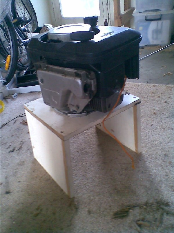
I found a problem with my engine; it wont start under any significant load. The second pulley I made meant it was extremely difficult to start.
I needed a clutch at some point anyway so I started thinking about how I could resolve both problems at once, removing as much load off the engine on startup and being able to clutch the engine.
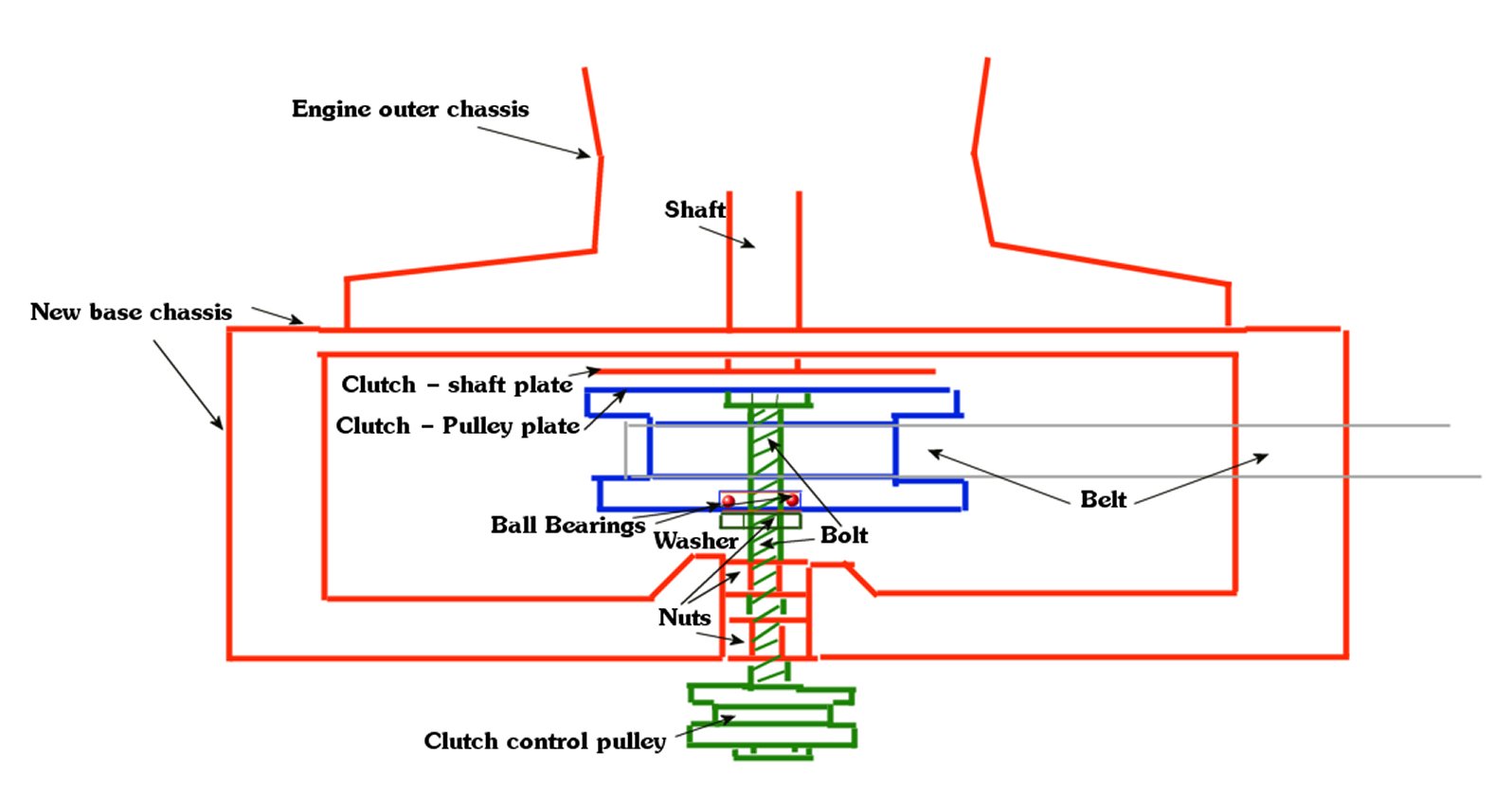
My plan is to put a small disk on the bottom of the shaft, then create a method of being able to push the pulley onto it; a dry friction clutch, but with a few changes. The clutch control will be a nut that I turn remotely (Likely by another pulley). The reason for this is it means I will be able to apply more force to the connecting plates via the bolt, and possibly later I may be able to automate it (ie, mechanical clutch)
Also it seems like it will be the easiest to build.
This is what I imagine it would assemble like (click for big)
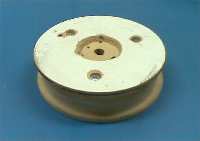
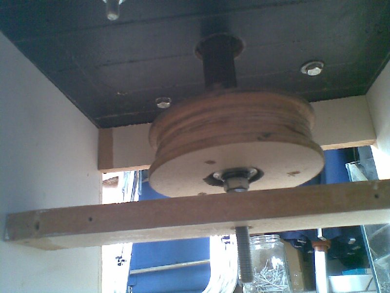
More detail on the bottom of the pulley:

The pulley will turn freely inside the bolt, I may later replace the bolt and bearings with a real bearing perhaps out of a skateboard or something. The bolt pushes the pulley up using the two lower fixed nuts, turning the bolt inside them will push itself up up.
Update 16 July 2010
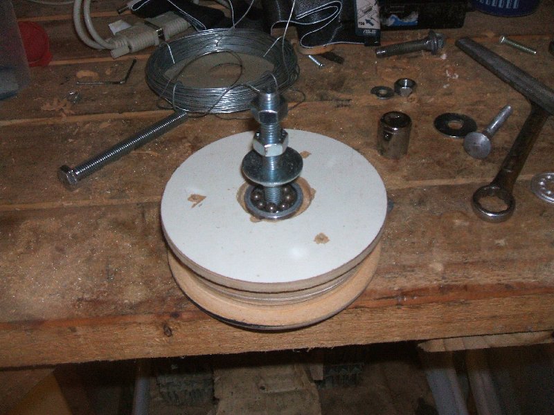
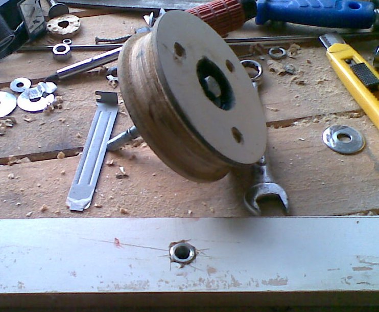
I started working on the pulley/clutch shaft and bearing. I spent most of the time trying to hammer, screw, grind some washers to the right shape. the most successfull was one that I ground down with an angle grinder except for the middle, then bashed the sides up a little bit. I found a aluminium ring which I think came from a hard drive and installed that and it seems to hold everything quite nice. Its not anywhere near perfect, not even near good, but its usable for now.

(Click for big)
The left picture shows an exploded simulation of how the bearing fits together, surprisingly this doesnt work too bad. The right image shows what it could look like assembled. Note the bit that says ‘Clutch Control’ this is just a bolt and two washers for image purposes. I need to put some thought into how I will turn the shaft, without allowing the spinning pulley to have any control over it. if I used a smaller pulley down the bottom or in the middle (as pictured), I fear it would be too easy for it to slip and the engine would dis-engage the clutch automatically. I also found I will need to modify the holes that the top bolt and bearing fit into; they are too shallow.
Update 17 July 2010
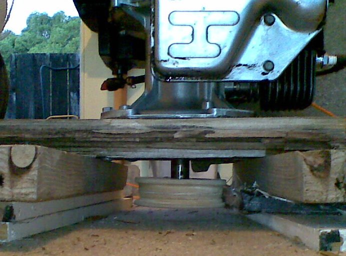
Started building the new base, and resunk the pulley so I had more bolt to play with, I am pretty happy with it. then I sunk a bolt into a wooden beam to go under the engine shaft, I shaped it with a craft knife, chiseled it out a little bit, then wacked it in with a hammer. It feels really solid so I am happy with this part. I in the 3rd pic I have placed it roughly where I expect it to sit. But I noticed I will have to be quite precise, I dont want the too shafts to be mis-aligned because it will mean the clutch plates wont sit true.
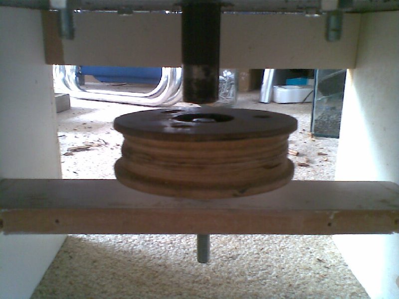
I still havent figured out how I can turn the clutch shaft without using too much bolt real estate and keeping it secure so its not able to be spun by the engine. although I am thinking about two small pulleys with some rope attached and wraped around a few times. buy pulling one rope, the pulley will spin the shaft and the height will increase, at the same time another pulley will be pulled and wrapped around the second pulley. I can then pull the second rope to do the opposite.